Convert Your Old Fashioned National Acme Multispindle Screw Machine Into A State Of The Art, Programmable Work Horse!
In late 1999, Jem Automatics with its ongoing vision for continuous improvement introduced its proprietary TechDrive screw machine conversion. This state of the art, programmable component contains numerous features and benefits which are the heart and soul which drive today’s complex, high efficiency multispindle screw machines. These features and benefits include but are not limited to the following, as compared to a standard Acme Gridley screw machine:
- Increased top R.P.M.
- Far less maintenance and downtime due to fewer moving parts = increased productivity.
- No more high speed clutch, low speed clutch, roll clutch, and brake to maintain and adjust.
- Superior lubrication system.
- Many less gears and moving parts results in a quieter machine.
- NO HAND CRANK! Power crank the cam shaft axis with MPG hand wheel or variable speed continuous jogging - forward and reverse.
- Power crank can be used with or without the spindles running.
- No more spindle speed and feed gear changes.
- Exact feed rate and spindle speed settings. No more compromising between available gear ratios.
- More precise low point, programmable to your job to maximize efficiency.
- Reduced cam changes can be achieved through simply reprogramming low point.
- Shorter cycle times can usually be achieved through ease of speed and feed fine tuning resulting in 10% to 40% improvement.
- Tool change control counter system for each position to notify operator or perform tool life study.
- Eliminates tool damage due to faulty brake or worn high speed clutch.
- FANUC 30i-B, 31i-B, 32i-B, or 0i-F series CNC controller (depending on number of axes) with touch screen control.
- Automatic “New Bar Trim” feature available to prevent tool breakage when using an auto bar loader.
- Save and Load job setup values to perform changeovers in much shorter time.
The custom operator software conveniently displays and monitors an array of options from production processes such as tool monitor, production speeds and feeds, system maintenance, feed time and much more.
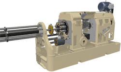
TechDrive Main Spindle Drive:
- FANUC spindle motor or high efficiency variable speed vector / inverter motor.
- Standard National Acme center drive shaft, bearings, and retainers.
- Durable FANUC spindle encoder to read spindle revolutions.

Feed Driven By Servo Motor:
- Feed servo motor mounted out of the way.
- Self contained right angle hypoid gearbox.
- Utilizes standard National Acme worm gear, bearings, and associated hardware.

Machine Upgraded with Motorized Lube Pump and Filter:
- Screw-on canister oil filter.
- Durable iron pump driven by electric motor, not by machine gear system.
- Differential pressure switch is installed so that the operator is notified when oil filter needs to be changed, therefore keeping the lube system at optimum quality and the machine at peak efficiency.


FANUC PMC/CNC Control System with Intuitive Touch Screen Controls:
- User friendly front-end operator software custom designed by JEM specifically for multispindle screw machines.
- Familiar FANUC back-end environment for on-screen G-Code part programming with interpolating CNC slide applications.
- Touch screen control can be configured for special attachments, bar loading system interface, and automatic loaders on chuckers.
- Main operator station can either swing fully to both sides of machine or an auxiliary push button station can be provided.
- No Hand Crank! Power crank with the MPG hand wheel forward or reverse from both sides of the machine, without running the spindles!
- Compact two-door (back-to-back) main control panel on wheels independent of the machine structure with quick plug-in connections.
- Job setup configuration values easily exported and imported to simplify part changeover
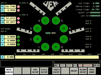
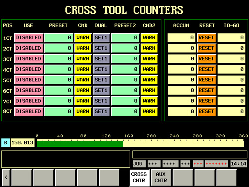
The Main Screen (shown in the photo below) is the screen you would leave up during automatic cycle. Real-time status of spindle RPM, drum position, spindle number locations, tool and part counters, cut time and total cycle time, CNC slide cycle time, automation status, possible alarms, and other relevant information is displayed here for easy observation.

|
|
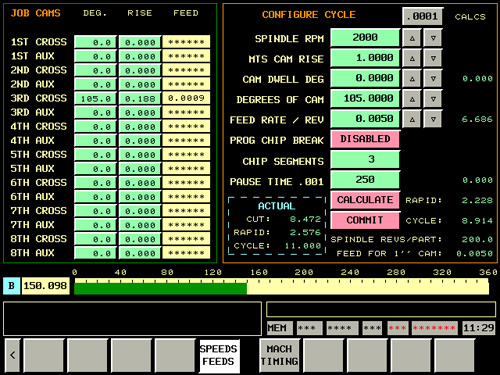
Setting spindle speed and cam shaft feed rate is configured with ease from the Speeds/Feeds screen. On the right half of this screen, simply enter the desired spindle RPM, the specifications of your installed main tool slide cam, and the desired feed rate per rev. Additionally, the programmable chip break function can be enabled which simulates a chip break cam by quickly pausing the cam shaft for the amount of milliseconds entered, and for the number of chip breaks desired. On the left half of the screen, physical job cams that may be installed in each position can optionally be entered to display the calculated feed rate for each of those tools. This calculation takes into account how you configure your main cycle, just like changing a set of feed gears on a mechanical machine. All of the values entered throughout the custom screens are stored and can be imported/exported in a single file to ease and quicken changeovers. |
|
|
Additionally, a second preset value could be entered for each tool if desired. For instance you could set to warn after 5000 and then stop after 6000. If performing tool wear study, the accumulated count can continue if you decide to not change the tool and not reset the counter. |
|
|
From this screen all manual controls can be performed either individually or by step sequence. The buttons double as indicators to show real time positioning, and the thin indicator bar underneath or next to each button shows where the next step is going in the sequence. This becomes helpful in case of an alarm, as a mismatched indicator can provide diagnosis at a glance. |
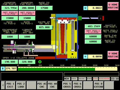 |
The inserting servo cylinder in this application has two forward positions, because the blank was ball ended and we first had to lower a leveling support once the neck was started into the spindle collet, and we could then continue to advance the blank to the precise position for machining. Each movement also has a configurable rate, unlike an air cylinder. |
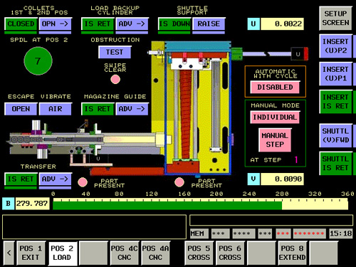
In the case of homing the servo motors, a button is provided for each axis that will perform an automated homing sequence. This automated routine eliminates the variation in reference position setting that arise depending on the operator. The axis will slowly move towards the hard stop, sense the torque, and then move a pre-determined distance which is preset in the machine parameters as the reference position.
Optional 2-Axis CNC Cross Slides or Single Axis Servo Cross Slides:
- Industry standard G-Code programming for our 2-axis CNC cross slides
- Conversational programming with our custom front-end software for 1-axis servo slides
- Rough rise and feed rate, then finish rise and feed rate, then dwell can be applied
- Independent electronic chip breaking function at each single axis servo station
- Spindle identification switching for automatic indexing error offsets
- Automated servo homing sequence eliminates reference position variations
- Single axis servo conversion utilizes the Acme Gridley slide for tooling compatibility


Additionally, if all machining cross slides and any utilized auxiliary slides are converted to servo control and no longer driven by the cam shaft, then the machine can run as a "full CNC" even though the main tool slide is still cam operated. A tool slide cam is installed with the longest rise you would possibly need, and if the desired rise is shorter than the installed cam, the servo drum remains at rapid speed past standard low point until the desired rise is what remains. The servo then decelerates to run the tool slide at the programmed feed rate for the remainder of the cam.
As with the other single axis cross slides, a rough rise and feed rate and then a finish rise and feed rate and then dwell can be applied as well as chip-breaking pauses. The independent axis main tool slide could also be utilized for machining such as peck drilling or other repetitive movements based on your setup.
Specifications of a Remanufactured Acme Gridley Screw Machine converted to TechDrive:
This list is non-exhaustive and is only an overview of the services we provide for the typical multispindle bar machine TechDrive conversion. Some items below may or may not be included or applicable based on your specific screw machine. Furthermore, additional services pertaining to spindle stopping machines, high speed chucking machines, collet chuckers, and hydraulic chucker screw machines may not be itemized below. Please refer to your quotation for the specific lineup pertaining to your screw machine project.
- Carrier And Headstock:
- Carrier assembly is cleaned and totally disassembled.
- Carrier stem is inspected, measured and case hardness determined.
- If case hardness of stem is determined to be within tolerance, the stem will be reground.
- If case hardness would be out of acceptable limits, the stem will be pre-ground, chromed and finished ground.
- Main toolslide bushing replaced and bored to fit new carrier stem diameter.
- Carrier O.D. bearing diameters are inspected and measured.
- New Timken Class 3 spindle bearings installed.
- Front and rear retainers are replaced.
- Optional - Center drive and spindle gears are replaced with new, heat treated and ground gears for longer life and lower vibration at higher speeds.
- Optional - Work spindles modified with ceramic journal, special retainers with seals installed.
- Optional - Carrier journals and headstock bores are modified for carrier seals. Headstock and carrier drilled for individual bearing bore lubrication.
- Main Tool Slide and Cross Slides:
- Main tool slide is cleaned and inspected. Damaged areas are repaired and reworked.
- Main tool slide bushing replaced and bored to fit new carrier stem diameter.
- Flat and taper gibs to be replaced.
- The nut, spacer and positive stop rod replaced.
- New standard size push rod bushing installed in gear box.
- Tool slide operating arm repaired and fitted with new roll and stud.
- All main tool slide holders shall be replaced and line bored after completion of quality assurance testing.
- All cross slides are disassembled, cleaned and repaired as necessary.
- All wear elements replaced.
- Cross slide assemblies are then ground/scraped for fit and returned to OEM specification center heights.
- Index Mechanism:
- Locking pin assembly is inspected and locking pin is ground and mated to locking pin sleeve if necessary.
- Locking lever fitted with new rolls and studs.
- Locking pin spring replaced.
- Locking pin cam replaced if necessary.
- Replace index gear shaft.
- All rolls, studs and bushings replaced with new.
- All shaft, bushing and spacers are replaced.
- Gear Box Section Conversion to TechDrive with Variable Speed:
- All drum drive train components (including drums and shafts) replaced or repaired as necessary.
- All gearbox and headstock shaft and bearing bores are inspected and repaired as necessary.
- Worm shaft assembly to be replaced with new TechDrive assembly
- All standard spindle drive mechanism to be replaced with new TechDrive components
- Lube System:
- New motorized lube pump installed.
- All new lube lines and fittings are installed.
- New lube oil intake screen installed.
- New screw-on canister style lube oil filter assembly installed.
- Pressure switch to shut machine down when not enough oil pressure in system
- Pressure switch to indicate need to change filter.
- Electrical System:
- All new enclosure, components, and wiring installed.
- Main control station with FANUC color touch screen and physical push buttons for standard operations.
- Secondary push button control station when main control station cannot swivel to both sides of machine.
- Spindle encoder for feedback of spindle revolutions provides precise feed rates that follow the spindles.
- Custom software designed by JEM specifically for multispindle screw machines.
- Three phase 480VAC standard. Other voltages optional.
- Motors:
- FANUC spindle motor or high efficiency vector / inverter motor for variable speed spindles.
- FANUC servo motor and drive system installed for drum shaft drive train.
- FANUC servo motors for optional CNC slides or other automated motion control functions.
- Reassemble:
- The machine shall be completely reassembled To OEM specifications.
- Quality Assurance:
- Radial, spacing and straightness test are performed on all spindles. These tests will meet or exceed OEM specifications.
- Our customers are invited and encouraged to visit during the machine rebuild program and especially to witness our quality assurance testing.
- Test results are submitted with all machines.
- Paint:
- Machines are painted to customer specifications.
- Paint specifications are requested to be included in the purchase order.